
Project management
Creating projects, organizing sets, and managing images
Creating a project
Select "New Project" on the project list screen.
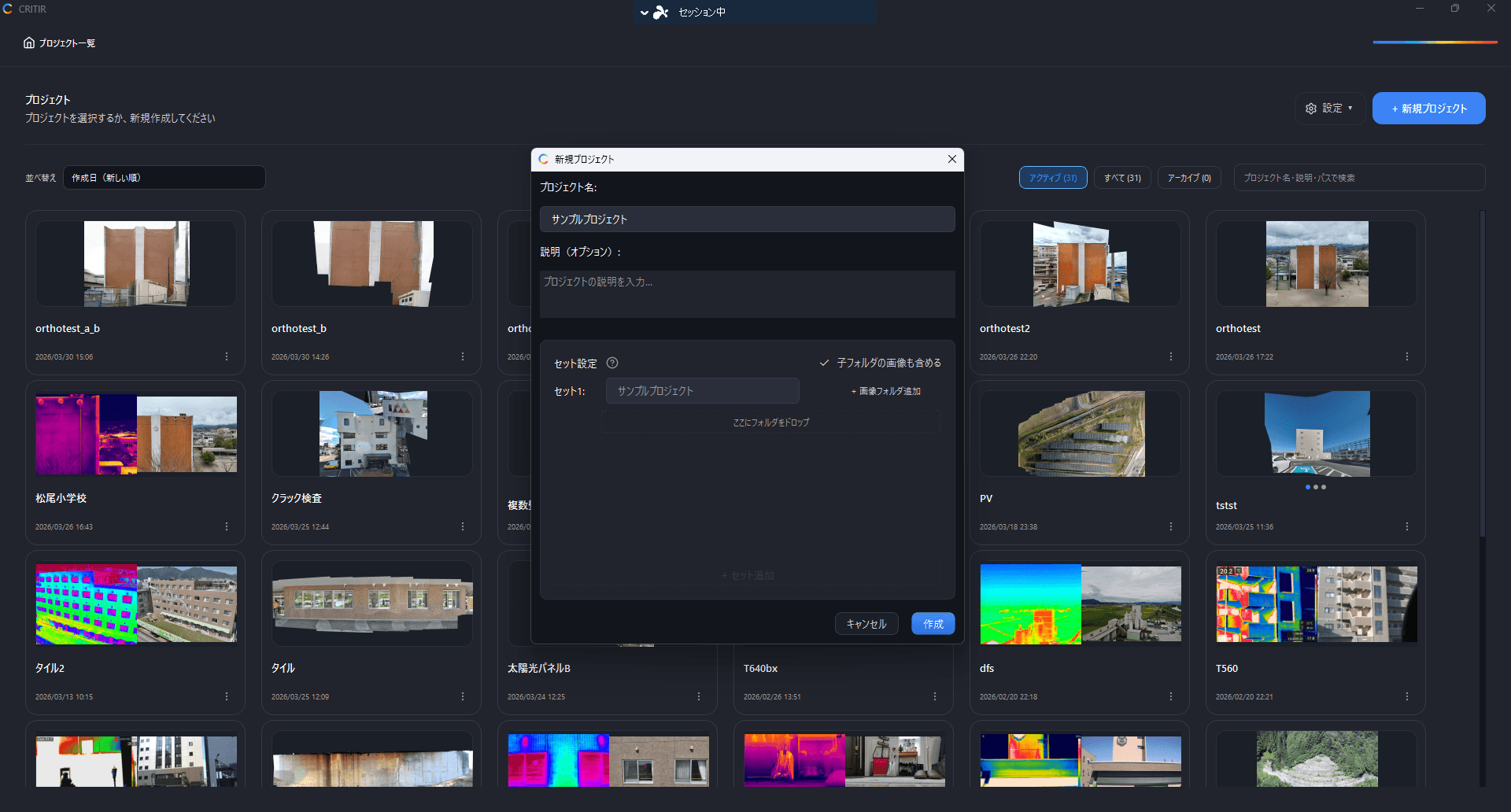
Basic settings
- Project name (required) — Enter a name that identifies the project, such as the building name
- Description (optional) — Free-form notes or remarks
Configuring sets
A set is a unit for grouping images. Orthomosaics are generated per set, so put each facade of a building (north face, south face, and so on) in its own set.
- Assign one or more image folders to each set
- Click "+ Add Set" to add another set
- Folders can be added to or removed from each set individually
For cylindrical or curved buildings: For targets with curved walls — tanks, silos, round buildings — a per-facade planar orthomosaic is not a good fit. In that case, group the images captured all the way around the building into a single set, generate a 3D mesh, and inspect and measure on the 3D model instead. If you want the whole circumference as a single unwrapped image, cylindrical unwrap is available once the 3D mesh exists.
Adding image folders
To align infrared and visible images, both must be located in the same folder.
Finishing creation
Click "Create". The images in the specified folders are scanned automatically, and the main screen opens.
Automatic fine alignment during import
When images are imported, fine alignment runs automatically for newly completed visible and thermal image pairs. When adding images to an existing project, it targets the newly imported pairs. Existing manual adjustments are preserved.
Check the alignment in overlay mode after import. For further adjustments, use fine alignment in the viewer.
Managing the project list
The list screen — shown right after startup, or opened with the Projects button at the far left of the toolbar — is where you organise your projects.
Filtering and sorting
| Control | Options |
|---|---|
| Filter | Active / All / Archive (each shown with a count) |
| Sort | Creation Date (Newest First) / Recently Opened / Name |
Per-project menu
Use the button on each card.
| Action | Description |
|---|---|
| Open | Opens the project |
| Open Folder | Opens the project's folder in Explorer |
| Rename | Renames the project |
| Copy Project | Duplicates it under a new name (see below) |
| Export... | Writes it out as a single file. See Export › Exporting projects |
| Archive / Unarchive | Hides it from the list, or brings it back. No data is deleted |
| Delete Project | Deletes the project |
Copying a project
You can choose between two copy scopes.
| Scope | What is duplicated |
|---|---|
| Copy All | Images, SfM, orthomosaics, measurements, reports and 3D products |
| Images Only | Set structure and image folders only (no SfM, orthomosaics, measurements or reports) |
Images Only is handy when you re-shoot the same site and want to carry over just the configuration. Duplicate project names are not allowed, so give the copy a new name.
Archive only hides a project from the list — its data remains. Switch the filter to Archive or All to unarchive it at any time.
Filtering images
Use the controls at the top of the image list panel to narrow down which images are shown. This is handy when you are looking for specific images among hundreds.
| Control | Description |
|---|---|
| All Images / Infrared Images / Visible Images / Zoomed Images | Filter by image type using the tabs (counts shown in parentheses) |
| Search by filename... | Filter by part of the filename |
| Filter button | Opens a panel to filter by judgment, type, part and processing state (see below) |
Filter panel
Press the Filter button to open a panel with one row of choices per axis.
| Axis | Choices |
|---|---|
| Judgment | Normal / Needs Review / Needs Correction, etc. (the same judgment presets as the inspection table) |
| Type | Delamination / Crack, etc. (the same type presets) / No type |
| Part | Wall / Column / Beam, etc. (the same part presets) |
| Measurement | With measurements / Without measurements |
| Image link | Linked / Not linked |
| Ortho | Used / Excluded |
| Culling | Kept / Excluded |
| Inspection | Inspected / Not inspected |
- Selecting several choices within one axis keeps images that match any of them (OR); combining axes keeps images that match all of them (AND). An axis with nothing selected is ignored
- The count next to each choice is the number of images after the image-type tab and filename search, before the axes are applied. It does not change when you toggle other axes
- While a filter is active the button reads Filter (N) (N = number of axes with a condition) and its tooltip lists the conditions. The panel header shows Showing N / M, and the image-type tab counts reflect the filtered result
- When no image matches, the list shows "No image matches … at the same time." together with a button such as Remove the "Judgment" condition (→ 12 images) for an axis that would bring results back
- Clear all removes every condition at once
Marking images as inspected
Click the badge in the top-left corner of a thumbnail to mark the image as inspected (a green check badge). Click it again to clear the mark. Besides tracking which images you have reviewed, it also works well as a flag for images of interest you want to revisit later.
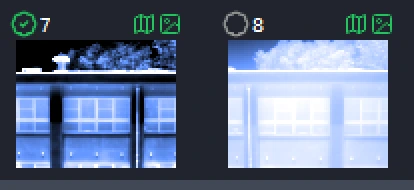
You can also select multiple images, right-click, and choose Mark as Inspected / Clear Inspected to set them in bulk.
When an image is marked as inspected, its camera frame is shown filled in the ortho viewer, so you can see inspected and uninspected areas at a glance.
Culling by location
From Process ▾ → Cull by Location on the toolbar, you can automatically exclude duplicate images captured while hovering and the like. Running this before image linking, 3D reconstruction, or orthomosaic generation shortens processing time.
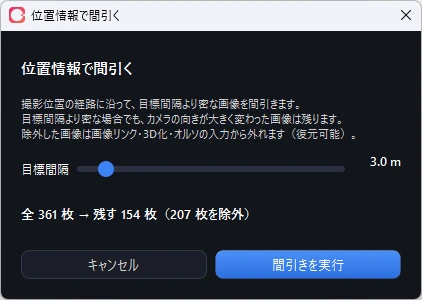
Move the Target spacing slider (0.5–30.0 m, default 3.0 m) and the result updates instantly, e.g. 361 total → keep 154 (207 excluded). Click Run Culling to apply.
How culling works
Following the capture path, an image becomes an exclusion candidate when its distance from the previously kept image is below the target spacing. Because this is not a simple "keep 1 out of N" rule, bursts from slow or hovering segments are consolidated without leaving gaps in fast-flight segments.
In addition, the following images are always kept, even where spacing is dense:
- Images where the camera heading (yaw) changed by 25° or more, or the tilt (pitch) changed by 20° or more
- The first and last images of the capture
- Images without GPS information
Culling is non-destructive. Excluded images are only removed from the inputs to image linking, 3D reconstruction, and orthomosaic generation — they are never deleted. Re-run with a looser target spacing to bring them back.
Sets without location (GPS) information cannot be culled. In that case the slider and the run button are disabled, and the message "Cannot cull: no location data." is shown.