
Ortho viewer
Display modes and operations for orthomosaics
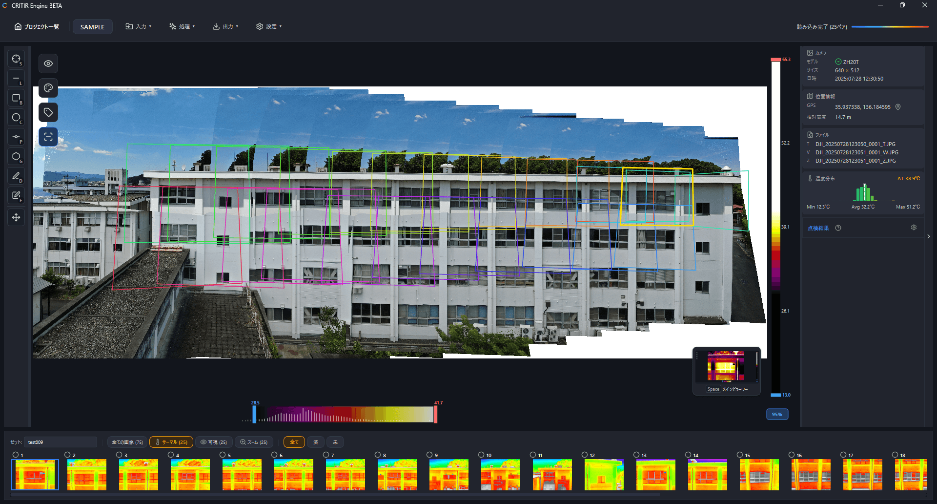
Once an orthomosaic has been generated, switch to the ortho viewer with SPACE or via the minimap at the bottom right of the screen.
Display modes
Switch modes with the display mode button on the toolbar.
| Mode | Description |
|---|---|
| Visible Image | Shows the visible orthomosaic |
| Infrared Image | Shows the infrared orthomosaic |
| Blueprint | Shows the loaded blueprint |
| Overlay | Overlays the visible, infrared, and drawing layers; the opacity of each can be adjusted with sliders |
Loading and aligning a blueprint
Loading a blueprint and overlaying it on the orthomosaic lets you locate defects on the drawing. It is also required for deterioration map reports.
Blueprint alignment requires an orthomosaic. Run orthomosaic generation first.
Loading
Load it from Input ▾ → Add Blueprint File on the toolbar. Load Blueprint on the blueprint-mode toolbar opens the same dialog.
Supported formats are DXF, PDF and images (JPG, PNG, BMP, TIFF). You can drag & drop a file instead of picking one from the dialog.
Specifying four corresponding points
The alignment screen opens once the file is loaded. Click four points that mark the same locations on the orthomosaic and on the blueprint, in order (1 → 2 → 3 → 4).
- Choose points you can identify reliably in both, such as building corners or opening corners
- Accuracy improves the more widely spread the four points are
- Clear All starts the selection over
- Once four points exist on both sides you can Save
Re-aligning and deleting
The Blueprint Alignment button on the blueprint-mode toolbar reopens the screen so you can redo the corresponding points at any time. Delete Blueprint on that screen removes the loaded blueprint.
Temperature on mouse-over
While the infrared orthomosaic is displayed, hovering the mouse cursor over the image shows the temperature at that point next to the cursor, e.g. 23.4°C. Nothing is shown over pixels without temperature data.
Camera frames
The orthomosaic shows the approximate capture area of each photo, and clicking a frame opens the corresponding photo.
Toggle the display on/off with the camera frame button .
Inspection checklist
Each image in the image list panel has a checkbox you can tick once the image has been inspected.
When an image is checked, the inside of its camera frame is shown filled on the orthomosaic. This gives you a visual overview of inspected versus uninspected areas directly on the orthomosaic.
Measurement projection
Measurements made on individual photos are projected onto the orthomosaic.
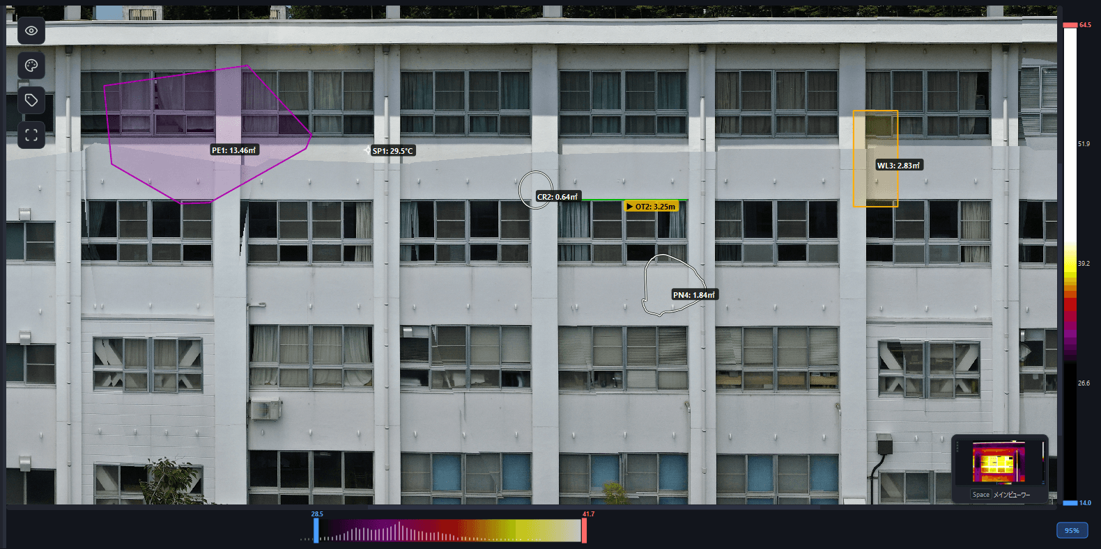
Rotation and guide grid
Rotate the orthomosaic from the Rotate dropdown on the toolbar (in 90° / 1° / 0.1° increments, clockwise or counterclockwise). While the rotation panel is open, guide grid lines (a center cross plus an evenly spaced grid) indicating screen-space horizontal and vertical are displayed to help you adjust the tilt. Toggle them with the Horizontal / vertical guides checkbox.
Polygon crop
Use the Crop dropdown on the toolbar to cut away unneeded areas of the orthomosaic.
- Rectangle crop — drag to define a rectangular region
- Polygon crop — click to place vertices and define an arbitrary polygonal region
- Backspace / Ctrl + Z removes the last vertex
- Enter confirms
- Hold Alt while placing vertices to constrain them to horizontal/vertical
- Control the edit with Confirm / Cancel / Reset
GeoTIFF export
Top-down orthomosaics (horizontal surfaces such as the ground or a roof) can be exported as a GeoTIFF with absolute coordinates, ready to be georeferenced in GIS software such as QGIS.
- Right-click on the orthomosaic → Export as georeferenced GeoTIFF…
- Or select GeoTIFF as the format in the image export dialog
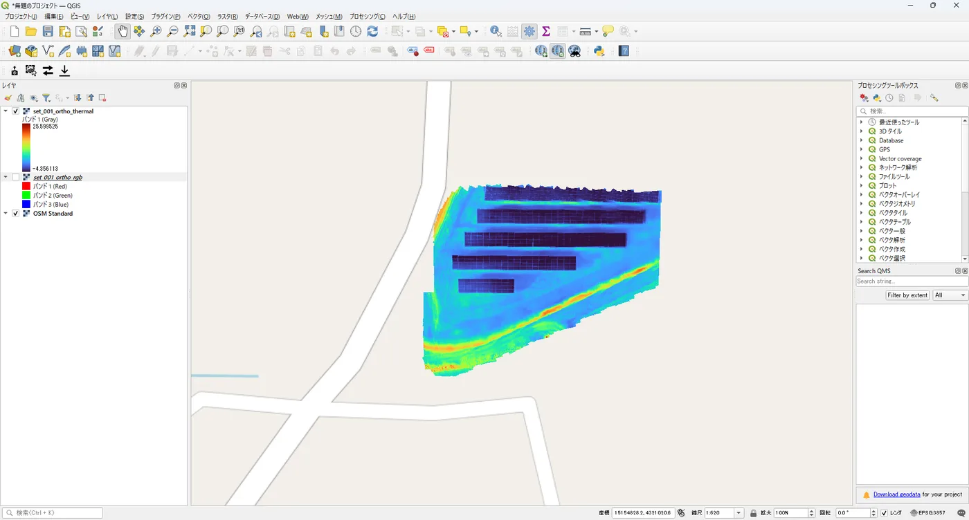
The RGB orthomosaic and the thermal temperature orthomosaic are each exported as a .tif, and the embedded EPSG code is shown on completion. The coordinate system (EPSG) is determined automatically from the UTM zone at orthomosaic generation time, so there is nothing to specify at export.
Georeferenced GeoTIFF export is only available for orthomosaics that have GPS information and cover a horizontal surface (ground or roof). Wall (elevation) orthomosaics and orthomosaics without GPS are exported as "no coordinates / local" and will not be georeferenced in GIS.
3D view
Use the 2D / 3D toggle button on the right side of the toolbar to switch to a CesiumJS-based 3D map view. You can review the orthomosaic, camera positions, and measurements in 3D space.
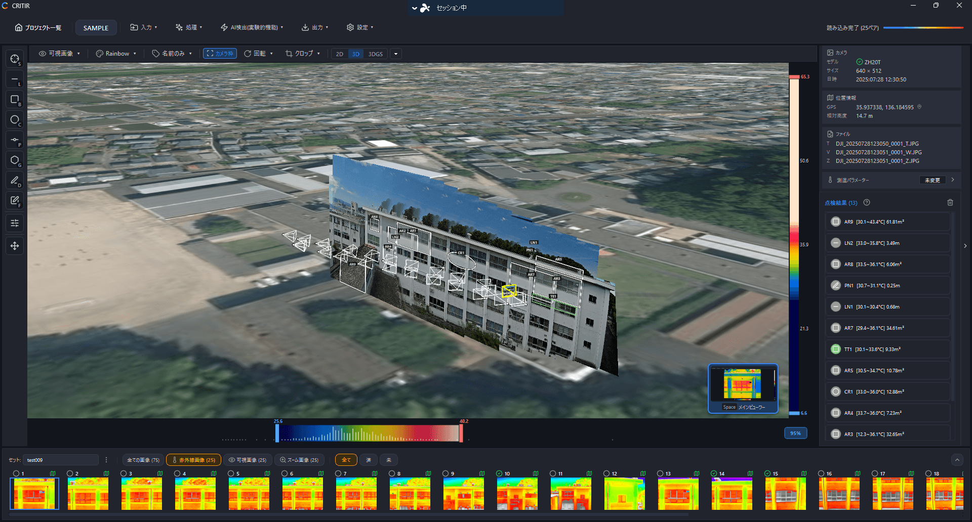
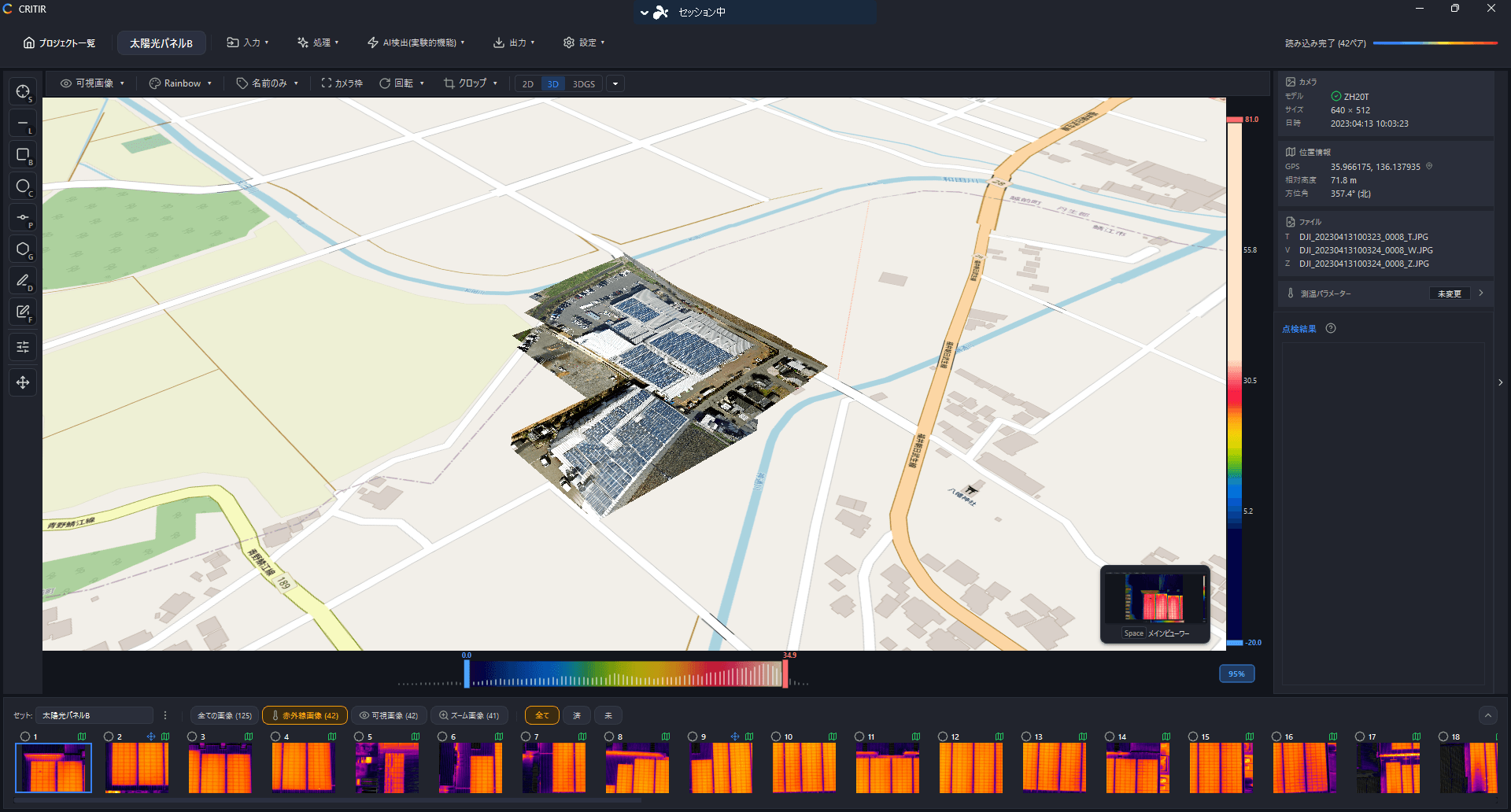
The background map tiles can be switched between three options: satellite imagery, standard map, and OpenStreetMap.
This 3D view (3D display on a map) requires an SfM result and GPS information.
3D mesh
If you generate a 3D mesh — a full 3D reconstruction of the subject itself — you can browse the 3D model from the 3D tab in the right side panel. You can also project measurements onto it and analyze a temperature 3D model with infrared data projected onto the mesh.
This is a separate feature from the "3D view (3D display on a map)" above. See 3D model for details.