
Orthomosaic generation
Wizard for generating wall-surface orthomosaics
What is an orthomosaic?
An orthomosaic is a front-facing composite image generated from multiple obliquely captured photos. It lets you view an entire building wall as a single image, which is ideal for understanding accurate spatial relationships and for inclusion in reports.
CRITIR can generate visible and infrared orthomosaics at the same time.
Launching the wizard
Launch image linking / orthomosaic generation from either of the following:
- Process menu on the toolbar → Image Linking / Orthomosaic Generation
- Orthomosaic generation button at the bottom right of the main viewer (shown when no orthomosaic has been generated yet)
Wizard steps
Step 1: Output settings
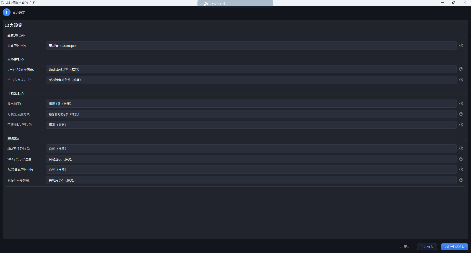
Output to generate
At the top of the output settings, choose Output to generate from two cards.
| Option | Description |
|---|---|
| Visible orthomosaic (default) | Generates only the orthomosaic from visible images |
| Visible + infrared orthomosaic | Also generates the temperature orthomosaic. Requires visible/infrared image pairs, and takes more time and disk space |
The Infrared orthomosaic items under Advanced settings can only be changed when Visible + infrared orthomosaic is selected. Sets with no image pairs cannot select Visible + infrared orthomosaic.
Resolution
The orthomosaic resolution is decided automatically from the ground sampling distance (GSD) of the photos and the extent of the target after image linking. There is no preset or pixel size to choose.
Generation method
Choose by whether the target is flat. Neither method is "better": on flat targets the planar orthomosaic is faster and gives a more stable result.
| Method | Suited to |
|---|---|
| Planar orthomosaic (default) | Flat walls, roofs, ground, and so on. The target is projected as a single flat plane |
| Surface-corrected orthomosaic (experimental) | Buildings and structures with relief, solar panels, and similar targets. A dense 3D point cloud is built from multiple images to recover the relief, and the images are projected along that shape. Requires well-overlapped images and takes longer |
Surface-corrected orthomosaic applies to both visible and infrared output. Depth estimation runs on a CUDA-capable GPU when one is present, otherwise on a DirectX 12 class GPU (including integrated graphics), and otherwise on the CPU. The result is identical in every case; only the processing time differs. When an existing 3D point cloud is available it is reused and generation takes minutes; otherwise it can take tens of minutes. On a PC where it is unavailable, the option reads Surface-corrected orthomosaic (not available on this PC) and cannot be selected.
When both a planar and a surface-corrected orthomosaic exist for the same face, you can switch between them at any time with the product switch in the ortho viewer.
Advanced settings
The defaults are recommended in most cases, but you can adjust the advanced settings if you run into problems.
Image linking settings
Under the output settings, Image linking settings lets you choose whether to compute image linking (SfM) afresh or reuse an existing result.
| Method | Description |
|---|---|
| Reuse existing result (recommended) | Keeps the same coordinate system as the existing 3D model and measurements. Available when a previous image-linking result remains for the same set |
| Compute image linking anew | Runs image linking from scratch. The coordinate system may change |
The Reuse section in the rail on the left of the wizard shows how existing products such as the image-linking result will be handled. Use Change… there to switch which products are reused.
Open Advanced image linking settings to change the following.
Moving to the next page
The button below the output settings reads Start Image Linking when SfM (image linking) will be computed, and Next (Target Surface) → when an existing image-linking result is reused (the button shows the process name when a long process starts, and the destination when the next page opens immediately). When image linking runs, the wizard minimizes itself after a few seconds and the main window shows a notification once it finishes. When an existing result is reused, the plane candidates from last time are restored as they were, so you move straight on to target plane selection.
Step 2: Set selection
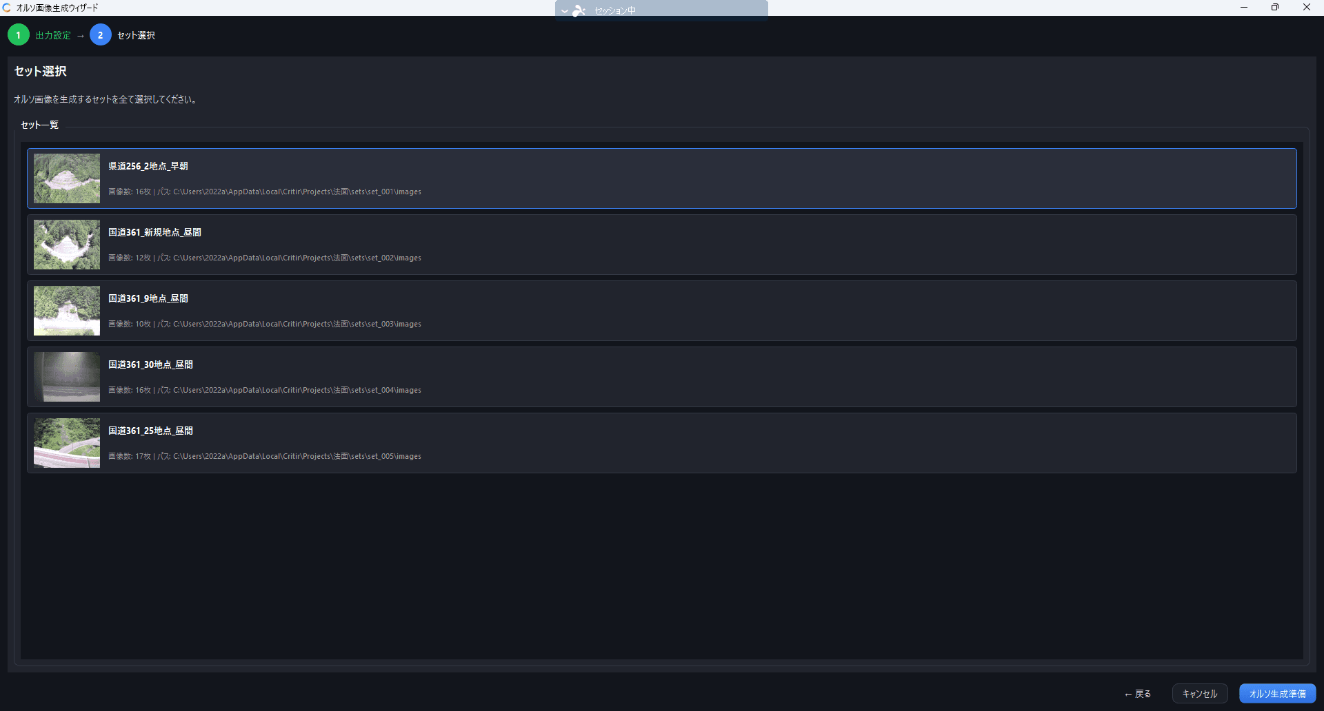
If the project has multiple sets, select the target set for orthomosaic generation. This step is skipped automatically when there is only one set.
Step 3: Target plane selection
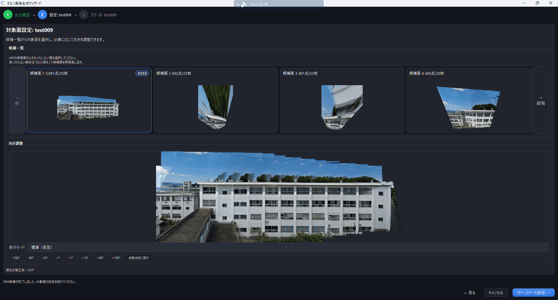
Candidate planes automatically detected from the SfM result are shown in a grid. Select the candidate that corresponds to the target wall surface.
- The most suitable candidate is marked with a "Recommended" badge
- If no candidate fits, click "Find More" to search for additional candidates
- Newly found candidates are marked with a "NEW" badge
Specifying a plane manually
Automatic detection looks for planes based on point-cloud density, so the plane you want may not appear among the candidates — the candidate list may be empty, the structure may be slender, or you may want only part of a wall. In that case, click "Specify Plane Manually..." and draw the target plane on an image to create a candidate.
- Pick an image from the thumbnails where the target plane is clearly visible
- Click the start point, move the mouse, and click the end point to enclose the target plane
- Click Add Area and Preview to generate a combined orthomosaic preview
- If needed, enclose the same plane on other images and repeat step 3 (selections across images are merged)
- When the preview looks right, click Save This Preview
| Action | Description |
|---|---|
| Preview controls | Scroll to zoom, drag to pan, double-click to fit |
| Remove Area from This Image | Cancels the selection on the currently displayed image |
| Clear All | Discards every area you specified |
The area you enclose is also used as the area included in the orthomosaic, which is useful when you want to crop out just the wall.
Saving adds it to the candidate list with that candidate selected.
Orientation adjustment (optional)
When you select a candidate, the orientation of the orthomosaic is estimated automatically. If needed, fine-tune it with the rotation buttons (±180° / ±90° / ±10° / ±1°). Click "Restore Auto Orientation" to reset to the initial state.
Step 4: Scale settings (optional)
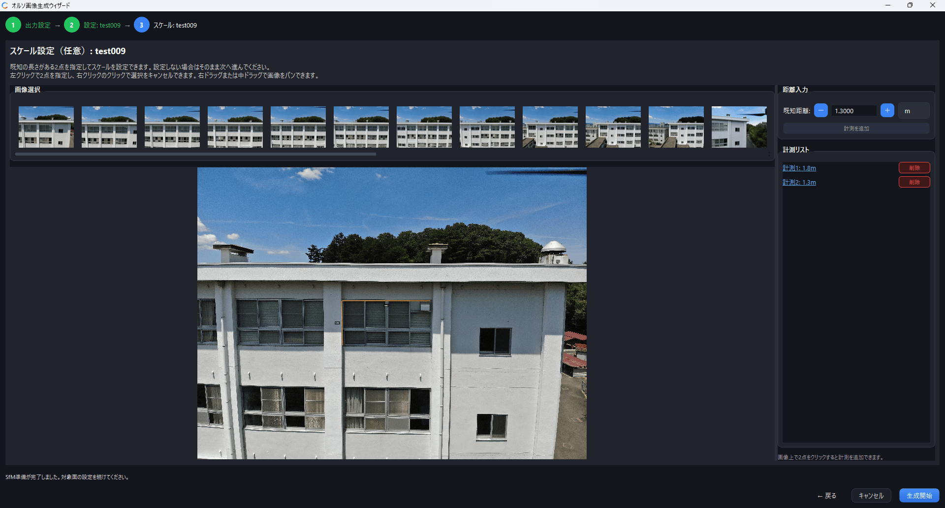
You can calibrate the real-world scale of the orthomosaic by specifying two points with a known distance between them. This step can be skipped.
- Click two points with a known distance on the image (e.g. a door height or window width)
- Enter the actual distance and unit (m / cm / mm)
- Click "Add Measurement"
Registering 2–4 measurements is recommended for better accuracy. Because the median of the measurements is used, the calibration is robust against outliers.
The scale you set here is a per-set setting: it applies not only to the orthomosaic but also to the 3D mesh, the cylindrical unwrap, and measurements on the original images. Even if you skip this step, you can set or correct it at any time from Process ▾ → Scale Settings. See Scale settings for details.
Starting generation
Once all settings are complete, click "Start Generation" and the orthomosaic is generated automatically.
Generation takes time depending on the number of images and your PC's specifications.
You can continue other work during processing, but you cannot switch projects or sets.