
How much overlap do drone photos need? Front overlap and sidelap explained with diagrams — shooting for good orthophotos and 3D models
How much should drone photos overlap when you want to build an orthophoto or a 3D model from them? This visual guide covers what front overlap and sidelap mean, why overlap is needed at all, the recommended values from Pix4D, Agisoft Metashape and Japan's national survey manual (and the conditions behind them), how to calculate shot spacing, what changes when you shoot a building facade, why thermal imagery needs more overlap, and why shooting too much also hurts.
Key takeaways
- Overlap is the share of a photo that its neighbor also covers. Overlap along the flight line is front overlap; overlap with the adjacent line is sidelap
- You overlap so that every point appears in several photos. One photo only tells you a direction; you need a photo from another position to fix where the point is
- Typical targets: 75–80%+ front overlap, 60%+ sidelap. More for forests, plain surfaces and thermal imagery. Every recommendation comes with conditions
- Shot spacing follows from distance and field of view. Facades are shot from close range, so the spacing is shorter than you might expect
- Overlap does not fix everything. Plain walls, glass and moving objects still cause trouble, and shooting too much slows processing down
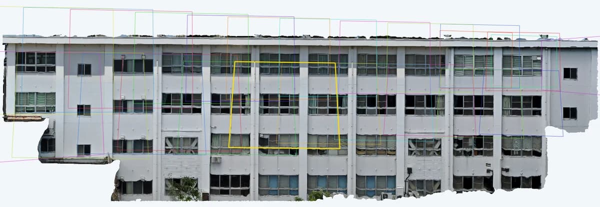
The colored lines mark, photo by photo, which part of the wall each picture covered (the yellow one is the selected photo). This school facade was turned into a single orthophoto from 25 photos. Neighboring frames overlap moderately, with no gaps anywhere.
Too little overlap makes processing fail, but more is not always better. So how much is enough?
You shoot a site, get back to the office, start processing — and some photos won't connect, or the orthophoto has holes. It is one of the most common failures in photogrammetry, and insufficient overlap is usually the cause. A reshoot means another trip to site. This article lays out, with diagrams, how much overlap you need and why.
What exactly is "overlap"?
Overlap is the proportion of the area in one photo that is also covered by the neighboring photo. If 80% of a photo's width is shared with the next one, the overlap is 80%.
Overlap has two directions.
- Front overlap (forward overlap): between consecutive photos on the same flight line
- Sidelap (side overlap): between photos on adjacent flight lines
Japan's national mapping agency, the Geospatial Information Authority (GSI), uses the same two figures in its manual for UAV public surveying, abbreviated in its check sheets as OL (overlap) and SL (sidelap).
The same idea applies when you shoot a wall. If you fly sideways along the wall, taking a row of photos and then moving up for the next row, the horizontal overlap is the front overlap and the overlap between rows is the sidelap.
Why overlap at all? One photo only gives you a direction
A single pixel in a photo only tells you "there is something in this direction from the camera". Whether that something is 2 m or 20 m away cannot be determined from one photo.
If the same point also appears in a photo taken from a different position, its location is where the two direction lines meet. That is triangulation. Software that builds 3D models and orthophotos from photos automatically finds points shared between photos (feature points) and solves this intersection for a huge number of them, recovering both the camera positions and the shape of the subject. The technique is called SfM (Structure from Motion).
Turn that around and anything that is not visible in at least two photos has no shape. The Agisoft Metashape manual states plainly that it can only reconstruct geometry visible from at least two cameras. In practice, automatic matching misses points when the viewing angle or lighting differs, so "just barely in two photos" is not enough. You want each point in more photos than that.
Overlap versus "how many photos see one point"
Along a single flight line, the number of photos a point appears in is roughly 1 ÷ (1 − overlap).
| Front overlap | Photos covering one point (approx.) |
|---|---|
| 50% | about 2 |
| 67% | about 3 |
| 75% | about 4 |
| 80% | about 5 |
| 90% | about 10 |
At 50%, most points appear in only two photos. Miss the match in either one and that spot is lost. At 80% there are five, so even if one or two fail, the rest still fix the position. That margin is why recommendations cluster around 75–80%.
What percentage? Recommendations from primary sources
Here are the figures published by the main software vendors and Japan's survey standard. Pay attention not just to the numbers but to the conditions they assume.
| Source | Subject / condition | Front overlap | Sidelap |
|---|---|---|---|
| Pix4D | General case (regular grid) | ≥ 75% | ≥ 60% |
| Pix4D | Flat agricultural fields | ≥ 80% | ≥ 80% |
| Pix4D | Forest / dense vegetation | ≥ 85% | ≥ 85% |
| Pix4D | Thermal images | ≥ 90% | ≥ 90% |
| Agisoft Metashape | Aerial photography | 80% | 60% |
| Agisoft Metashape | Aerial survey over forest | 90% | 80% |
| GSI UAV public survey manual, 3D point clouds | Actual overlap can be checked after the flight | ≥ 80% | ≥ 60% |
| Same | Actual overlap is hard to check after the flight | ≥ 90% | ≥ 60% |
A few patterns stand out.
- Low texture and movement call for more: tree canopies sway in the wind and look alike everywhere, so shared points are hard to find. Flat fields repeat the same pattern too
- Thermal is in a class of its own: thermal images have far fewer pixels, and Pix4D asks for at least 90% in both directions (more on why below)
- "If you can't check, add more": the GSI manual lets you plan at 80% when you can verify the actual overlap after the flight, and asks for 90% when you can't. Flights don't always go exactly to plan, so you build in margin
The same GSI manual sets 60% front overlap and 30% sidelap as the standard for traditional UAV aerial photogrammetry, where operators plot in stereo. If you see 60/30, it may not be a figure meant for building 3D models or orthophotos with SfM. Different goals need different overlap.
The GSI figures are a standard for producing terrain point clouds in public surveying. There is no legal overlap requirement for facade inspection. Still, the underlying mechanism — reconstructing shape from photos — is the same, so they are a useful reference.
Calculating the shot spacing
"80% overlap" is a goal. What you need on site is "a photo every how many meters, every how many seconds". You can work that out from the distance to the subject and the camera's field of view.
- Footprint of one photo W = 2 × distance D × tan(field of view θ ÷ 2)
- Shot spacing B = W × (1 − target overlap)
- Shutter interval (s) = B ÷ flight speed
For example, with a 70° horizontal field of view 10 m from a wall, each photo covers about 14.0 m. For 80% overlap the spacing is 14.0 × 0.2 ≈ 2.8 m. Flying at 1.4 m/s, that is one shot every 2 seconds. The GSI manual also requires the flight speed to leave enough time between shots for each image to be recorded.
Three easy mistakes
- Use the field of view along the direction of travel: spec sheets often list the diagonal field of view (DFOV), which is larger than the horizontal or vertical one. Flying sideways, use the horizontal FOV; flying up and down, the vertical FOV
- Overlap is set on the subject's surface: at the same spacing, the closer the surface, the narrower the footprint and the lower the overlap. In the example above, a balcony sticking out 2 m from the wall is only 8 m from the camera, so the footprint drops to about 11.2 m and the overlap to about 75%. From the air, rooftops and ridges higher than the ground get less overlap. The GSI manual warns that at low flying heights, small differences in height have a big effect on overlap. Plan so the part closest to the camera still meets the target
- Portrait vs. landscape matters: turning the camera to portrait swaps the horizontal and vertical fields of view
What changes when you shoot a facade
Aerial recommendations mainly assume a camera pointing straight down at the ground. Shooting the wall of a building changes a few things.
Close range means much shorter spacing
Aerial mapping is often flown tens of meters or more above the ground, while a facade may be shot from around 10 m. Footprint scales with distance, so the same 80% overlap means a spacing of only a few meters. Space your shots "the aerial way" and you run short of overlap fast.
Face the wall and shoot in a grid
The basic pattern is to face the wall squarely, take a row of photos sideways, then change height for the next row. CRITIR's shooting tips recommend 70–80% or more in both directions when shooting a facade by drone.
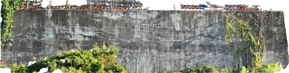
Watch out for protrusions and corners
- Eaves, balconies and louvers stick out toward the camera, so they get less overlap (see the calculation above), and what lies behind them can't be seen from straight on. Add photos from other angles where needed
- At building corners, include oblique photos that show both faces, to tie the faces together. If each face is shot in isolation, the software may not be able to work out how the faces relate
Subjects you circle around
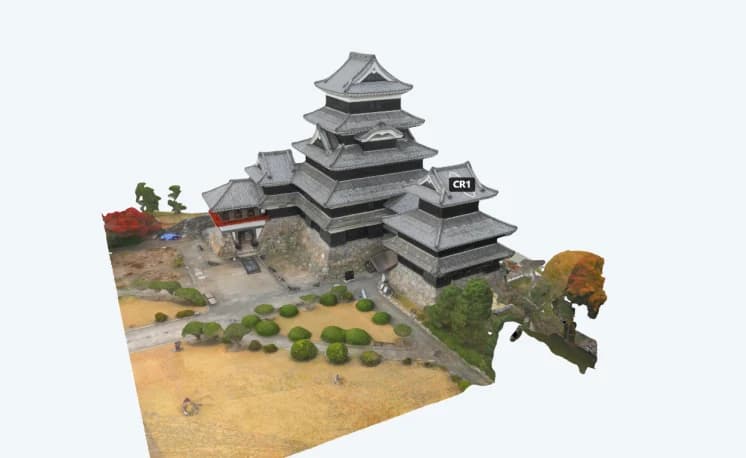
Towers and castles are shot by circling them. For orbits around a building, Pix4D recommends one photo every 5 to 10 degrees, depending on the size of the object and the distance to it — 36 to 72 photos per orbit. When you fly several orbits at different heights, make sure the orbits overlap each other too.
Give thermal more overlap than visible
When you build 3D models or orthophotos from thermal (infrared) images, increase the overlap further. Pix4D recommends at least 90% front and side overlap for thermal images, along with a resolution of at least 640×480 and images free of motion blur.
There are two main reasons.
- Fewer pixels, softer patterns: many drone thermal cameras are around 640×512 pixels, orders of magnitude fewer than a visible camera's tens of megapixels. Temperature patterns are often less crisp than visible detail, leaving fewer clues for matching points between photos
- Narrower field of view: on cameras that shoot visible and thermal together, the thermal lens usually has the narrower field of view. Shot from the same spot, the thermal footprint is smaller
The diagram shows a 70° visible camera and a 40° thermal camera shooting from the same spots 10 m from a wall. Spaced for 80% visible overlap, the thermal overlap is only about 62%. Widen the spacing to 40% visible overlap and a gap of about 1.1 m opens up between the thermal footprints. No photo records the temperature in that gap.
Re-check the spacing against the thermal footprint
Even when software aligns the photos using the visible images, a thermal orthophoto without holes needs the thermal footprints to overlap each other. It is safer to set the spacing by the narrower thermal camera, not the visible one.
What overlap can't fix
Overlap is necessary but not sufficient. Under these conditions, adding overlap may still leave the software unable to find shared points.
- Plain surfaces: pure white walls and uniform paint look the same everywhere, so photos can't be matched. Frame your shots to include textured features such as window frames, joints or neighboring walls
- Reflective or transparent surfaces: glass, water and shiny metal change their reflections with the viewing angle. The Metashape manual also advises avoiding untextured, shiny, highly reflective or transparent objects
- Moving things: branches in the wind, people and cars move between photos, so they can't serve as shared points
- Changing light: the Metashape manual advises against surveying the same area over a whole day, because shadows change direction and shape and the software may fail to find common points even in overlapping photos
- Blur, poor focus and zoom: blurred photos are useless however much they overlap, and changing the zoom (focal length) mid-shoot makes the camera calibration less stable
Too many photos is a problem too
"More is safer" is half right. For close-range work, the Metashape manual says more photos than required is better than not enough. But every extra photo adds processing time and storage, and the step that compares photos with each other gets heavier quickly as the count grows.
The most wasteful photos are those taken from almost the same spot while hovering or repositioning. Their overlap is close to 100%, yet they add almost no new information. Photos taken from nearly the same position also meet at a very shallow angle, so the pair on its own gives poor depth accuracy. The photos that pin down positions are those taken from reasonably separated positions.
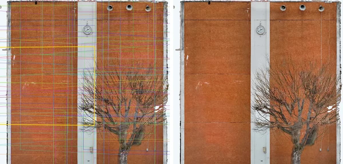
An over-shot example: 84 frames packed tightly together. The orthophoto came out well, but the same quality could have been reached with far fewer photos.
Compare it with the school building at the top and you get a feel for what "just enough" overlap looks like.
Secure the target overlap, then thin out obvious duplicates before processing. That is the best balance of time and quality.
Checking overlap in CRITIR
CRITIR is inspection software that builds facade orthophotos and 3D models from drone or ground photos. These features relate to overlap:
- Camera frames: the ortho viewer can draw each photo's footprint as a frame over the orthophoto (the image at the top of this article). You can see at a glance where coverage is thin, and clicking a frame opens that photo
- Badges on images outside the image link: photos that didn't connect during image linking (SfM) get a badge on their thumbnail, such as "No ortho" or "Unlinked" — a clue for finding photos that dropped out for lack of overlap
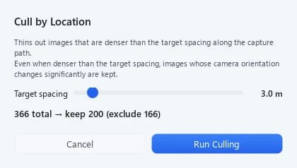
- Culling by location: automatically excludes duplicate photos, such as those taken while hovering, using a target spacing along the flight path. Exclusion can be undone
CRITIR runs image linking on the visible images, and the thermal images become temperature orthophotos and 3D models via their alignment with the visible ones. So overlap is judged on the visible images — but, as above, keep the spacing tight enough that the thermal footprints leave no gaps.
For more on shooting, see Shooting tips in the documentation; for building orthophotos, Ortho generation and Ortho viewer; and for thinning, Culling by location. For how orthophotos work, read What is an orthophoto?, and for 3D models, Generate 3D models from drone photos. For an overview of CRITIR, visit the product page.
Frequently asked questions
- Are "overlap", "overlap ratio" and "endlap" the same thing?
- Yes, they describe the same idea. Overlap along the flight line is also called forward overlap or endlap; overlap between adjacent lines is called sidelap or side overlap.
- If I increase front overlap, can I get away with less sidelap?
- No. More front overlap doesn't strengthen the connection between flight lines. With too little sidelap, the lines may be reconstructed as separate pieces, or holes appear between them. Keep both at the target.
- Does the same apply when shooting handheld from the ground?
- Yes. The footprint is set by distance and field of view, and you move a little at a time so each photo overlaps the last. From the ground you are often close to the wall, so you have to move in small steps.
- Is it enough to set the overlap in an automatic flight app?
- Flight apps usually calculate overlap for a flat surface at the height or distance you set. Parts that stick out toward the camera, or ground higher than the reference, get less actual overlap. Base your settings on the part closest to the camera and leave a margin.
Summary
- Overlap is the share of a photo covered by its neighbor. Along the line it's front overlap; between lines it's sidelap
- One photo only gives a direction, so every point must appear in several photos. At 80%, a point appears in about five
- Typical targets: 75–80%+ front overlap, 60%+ sidelap. More for forests, plain surfaces and thermal (Pix4D recommends 90%+ for thermal)
- Spacing follows from W = 2D·tan(θ/2), B = W(1 − overlap). Overlap shrinks wherever the surface comes closer to the camera
- Thermal cameras have a narrower view, so gaps can open in thermal coverage even when visible overlap is fine
- Plain, reflective and moving subjects and changing light aren't fixed by overlap alone. Thin out excess duplicates before processing
Sources
- Pix4D, "Image acquisition" (overlap for the general case, fields, forests and thermal; angle step for orbits around buildings)
- Pix4D, "Selecting the image acquisition plan type" (overlap, resolution and blur requirements for thermal images)
- Agisoft, "Metashape User Manual, Professional Edition, Version 2.0", Chapter 2 Capturing scenarios
- Geospatial Information Authority of Japan, "UAV wo mochiita kōkyō sokuryō manual (an)" [Manual for public surveying using UAVs (draft)], March 2016, revised March 2017 (copy hosted by MLIT Hokuriku Regional Development Bureau, in Japanese)
What is an orthophoto? How it differs from a photo, explained with diagrams — from aerial maps to building facades
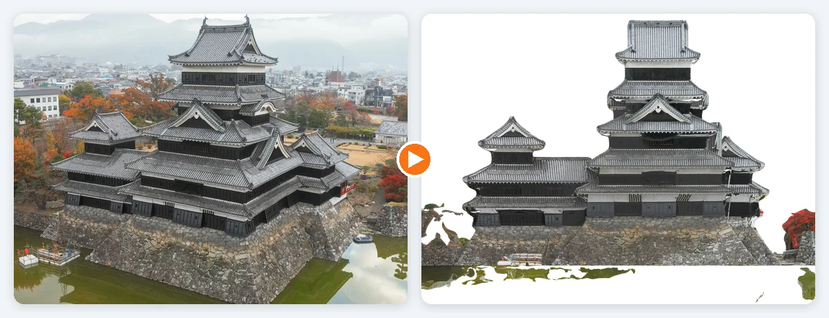
A visual introduction to orthophotos (orthoimages) and how they differ from ordinary photos. Covers relief displacement (why tall buildings lean outward), true orthophotos, the four steps from photos to an orthophoto, map orthos versus facade orthos, and the conditions where orthophotos fail — with real examples from Matsumoto Castle and a retaining wall.
Generate facade and wall orthoimages automatically with CRITIR
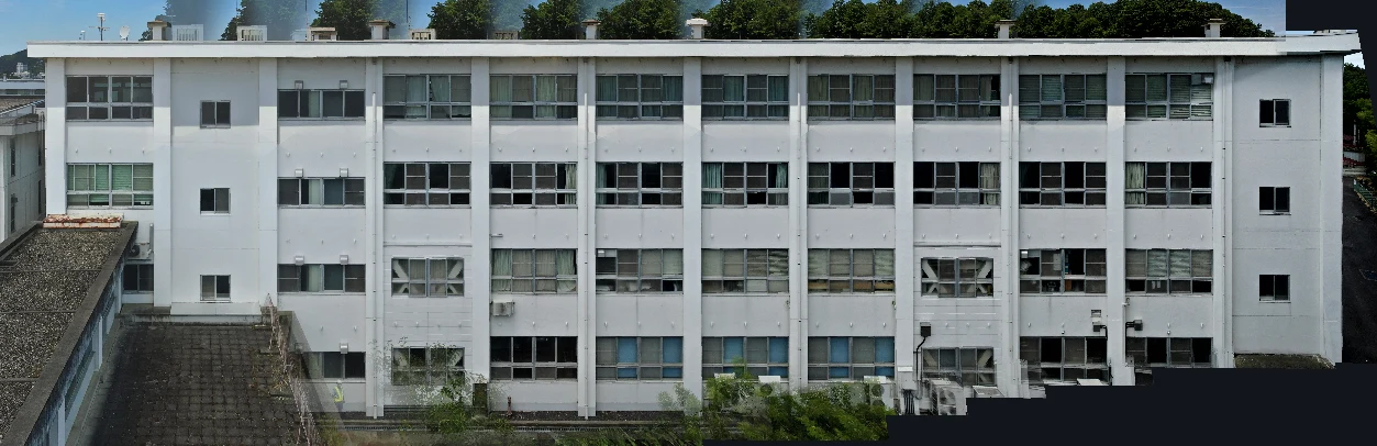
A clear walkthrough of how facade and wall orthoimages are built from drone or ground-camera shots, and how CRITIR simplifies the process. Where RealityCapture (RealityScan) and Metashape require significant manual work for vertical surfaces, CRITIR automates the pipeline — including thermal orthoimages — to streamline facade inspections and defect surveys.
Generate 3D Models from Drone Photos — Build Temperature-Colored (Thermal) 3D Models with CRITIR
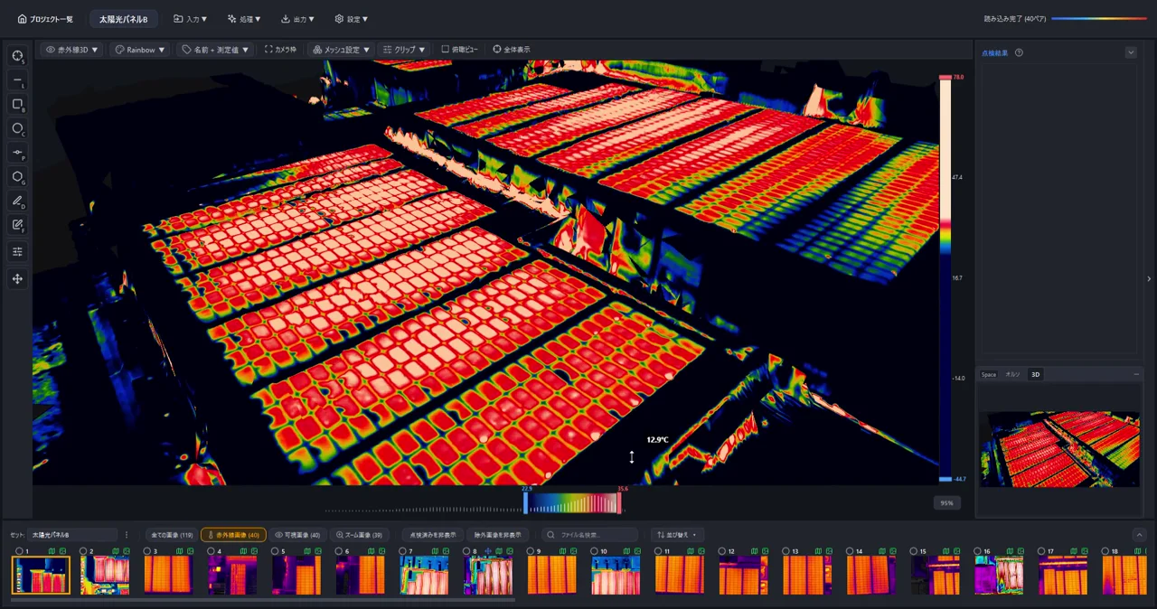
Learn how to automatically generate 3D models of buildings and structures from drone or ground-camera photos. With CRITIR, you get a visible-light 3D model plus a temperature-colored thermal 3D model, all linked to measurements and report output — streamlining inspection documentation for complex facades, equipment, and solar panels.