
Chimney and tank inspection on one unwrapped image: opening up the photos you took all the way around
Inspecting chimneys and tanks means you can never see the back, the photos split into dozens of shots, and it is hard to say where anything is in a report. This article explains the unwrapped development drawing (a rectangle for a cylinder, a fan for a tapered chimney), how such an image is built from photos, and what an infrared unwrap can and cannot tell you, using a real chimney as the example.
Key points
- Round structures are awkward to inspect. You see less than half at a time, the photos split into dozens of shots, and a report struggles to say where anything is
- The answer is an old one: the development drawing. A cylinder opens into a rectangle and a tapered chimney (a truncated cone) into a fan, without distortion, just like paper
- You can build one from photos. Slice the 3D model, measure how the radius changes with height, decide the shape, then open it out
- An infrared unwrap is a clue. It shows the temperature of the whole circumference at once, but always ask whether paint, sunlight or reflections explain a pattern
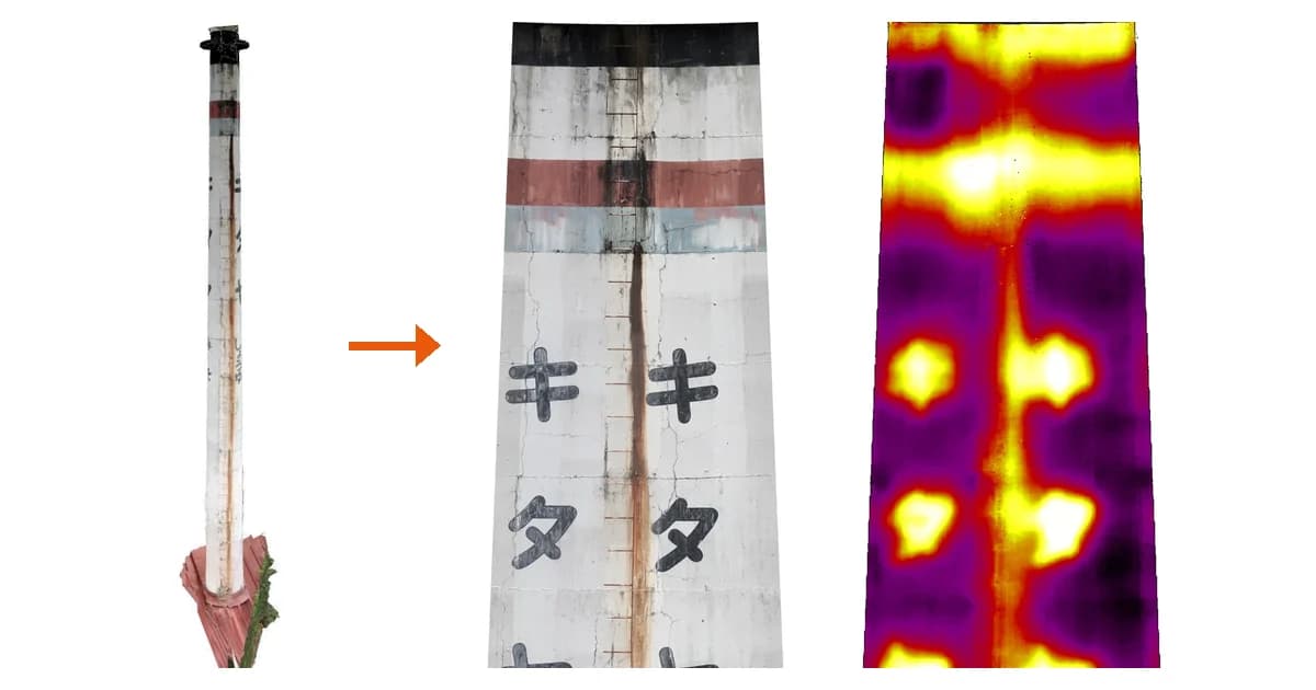
"Where was that rust streak again?" Three reasons round structures are hard
On a building facade, windows and corners are your landmarks. "Below the second window from the left on the third floor" points everyone to the same spot. Switch to a chimney or a tank and things get much harder.
1. You never see the back. Looking at a cylinder from outside, you see a little less than the near half. Near the edges the surface turns away from you, so cracks and rust look narrower than they are. The only way to cover it all is to walk around and shoot again and again.
2. The photos split into dozens of shots and lose their relationship. A chimney wall is the same colour and texture everywhere, with no corners and no windows. It all makes sense on site, but back at the office you find yourself asking whether this rust streak is the same one as in the last photo.
3. It is hard to say where anything is in a report. The best you can do is draw an arrow on a plan and add text like "north-east side, about 15 m up". The reader has to rotate the chimney in their head to picture the spot.
An old answer: think in development drawings
There is a long-standing answer to this: the development drawing. When sheet-metal workers make a pipe or duct, they first draw the 3D shape as a flat pattern. A cylinder becomes a rectangle and a tapering pipe becomes a fan.
Mathematically, cylinders and cones are developable surfaces: they can be laid flat without stretching or shrinking. A sphere cannot, which is why every flat world map distorts somewhere.
Cut a paper tube down one side and open it, and you get a rectangle whose width is the circumference and whose height is the height. Do the same with a tapered chimney (a truncated cone) and you get a fan-shaped band whose upper arc is shorter, because the circumference at the top is shorter. The left and right edges of the image are the two sides of the same cut.
Photos taken all the way around line up on one strip
The development drawing really pays off with inspection photos. Each photo taken while circling a chimney shows only part of the circumference. Put them back onto the development drawing and they line up in order along a single strip.
Compass directions become positions on the strip. If the cut is on the north side, "a quarter turn from north towards east, 15 m up" is a quarter of the way across the strip, 15 m from the bottom. Instead of describing a location in words, you can mark it on the drawing and hand it over.
How an unwrapped image is built from photos
So how do you get from a pile of separate photos to an unwrapped image? Roughly:
- Photograph all the way around the chimney with overlap (in several bands up the height)
- Build a 3D model from the photos (how a 3D model is built from photos)
- Estimate the axis and the radius
- Project the photos onto the estimated surface and open it at the cut
Step 3 is the key. To make the right pattern, you need to know which way the chimney points and how thick it is at each height.
In CRITIR, the rough direction of the axis comes from the camera poses. A drone gimbal keeps the camera level side to side, so the direction perpendicular to the horizontal axis of every photo is vertical.
Next, the surface of the 3D model is sliced into dozens of rings along the axis, and a circle is fitted to each slice. Points that do not sit on the circle, such as a ladder or a neighbouring roof, are discarded slice by slice. The resulting list of "radius at each height" decides the shape:
- Radius almost constant → a cylinder, opened into a rectangle
- Radius changes linearly with height → a truncated cone, opened into a fan
- Neither → reported as a shape that cannot be unwrapped
Finally, the photo pixels are projected onto the chosen surface. Because there is a 3D model, the software can also avoid painting a spot with the colour of something in front of it that actually blocked the view.
Why a tapered chimney stays a fan
Tall chimneys usually get narrower towards the top. What happens if you force one into a rectangle?
The narrow top gets stretched sideways and the wide bottom gets squeezed. For the chimney in this article, forcing it into a rectangle would distort the horizontal scale by about 1.25× at the top and about 0.85× at the bottom. The same size of spalling would look large near the top and small near the bottom.
Opened as a fan, the scale is the same everywhere. It looks a little odd, but you can measure lengths and areas on it directly.
A real example: opening up a town chimney
Now for unwrapped images of a real chimney. We flew a drone around it and built a 3D model.
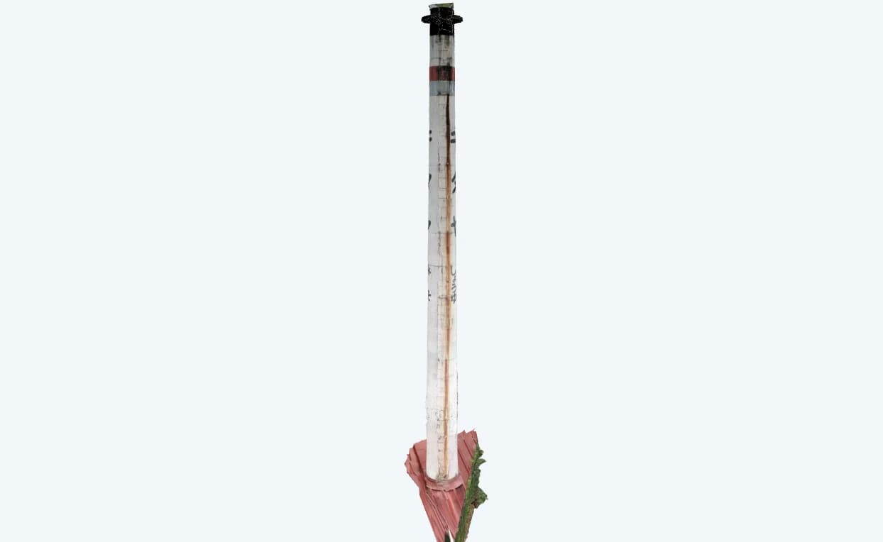
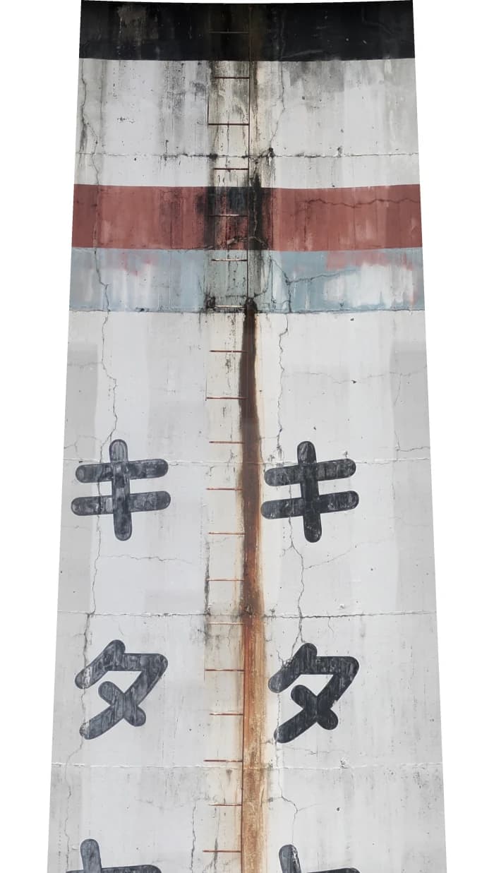
Opening it out gives the two images below: visible on the left, infrared on the right. You can see the slight fan shape, narrowing towards the top.
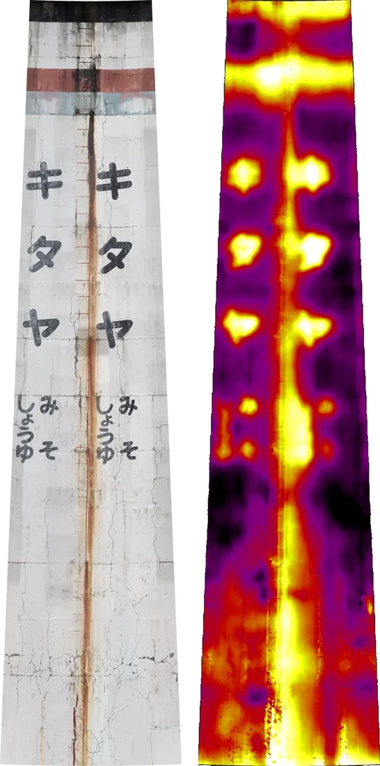
The first thing you notice is that the same lettering appears twice. Identical lettering painted at two places around the chimney ends up side by side. In photos, lettering near the edge of the chimney is squashed at an angle; on the unwrap both sets read as if seen face on.
In the visible unwrap, a rust streak running beside the ladder from the band down to the base, the worn painted bands, and a web of fine cracks can all be seen at once with their positions intact. Flicking through individual photos, just confirming that the streak is one continuous line from top to bottom would take real effort.
What infrared can tell you, and what it cannot
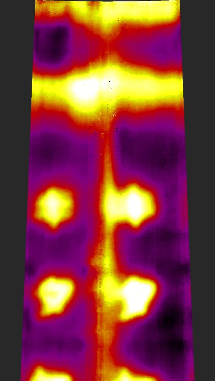
An infrared unwrap shows the surface temperature of the whole circumference in one image. But seeing a pattern is not the same as knowing its cause. This chimney makes a good lesson.
What are the hot spots on this chimney?
The bright round spots in the infrared unwrap line up exactly with the black lettering in the visible image. Black paint absorbs more sunlight, so the most natural reading is that the lettering itself is warmer. The bright vertical stripe in the middle also follows the rust streak and the ladder. Dark rust absorbing sunlight, or the metal ladder reflecting heat from its surroundings, could both explain it. Infrared alone cannot settle which.
Surface temperature, in other words, also depends on paint colour, sunlight and reflections from metal (see emissivity and reflected temperature). Seeing visible and infrared on the same unwrap makes it obvious that "this hot spot is a letter", which prevents jumping to conclusions.
That said, infrared does give useful clues in some situations:
- Chimneys in service: when flue gas heats the inside, localized hot spots on the outside are reported to indicate possible liner damage or gas leaks
- Concrete surfaces: the same principle as facade surveys applies, where delaminated areas trap heat and appear warmer after the sun has warmed the wall (why delaminated tiles show up in infrared)
- Tanks: the contents and the space above them warm differently, so on a sunny day the level of the contents can be visible from outside
All of these tell you where to look more closely. When you find a temperature anomaly, confirm it by other means such as close visual inspection or hammer testing.
Some older chimneys have insulation containing asbestos on the inside. Whether asbestos is present, and the condition of the inner insulation, cannot be judged from photos or infrared images taken from outside. Have it surveyed by a qualified specialist.
Some shapes will not unwrap
The development-drawing idea has a clear limit: only cylinders and cones (truncated cones) can be flattened without distortion, like paper.
| Shape | Unwrap | Why |
|---|---|---|
| Straight cylinder (tank, silo, round building) | Opens into a rectangle | Constant radius |
| Tapered chimney | Opens into a fan | Radius changes linearly with height |
| Bottle shape, waisted cooling tower | Cannot be opened | Radius changes along a curve, so it cannot be flattened without distortion |
| Spherical tank | Cannot be opened | A sphere is not a developable surface |
| Square chimney | Not unwrapped | It is a set of flat faces, handled with a wall orthoimage per face |
Even a straight shape cannot be estimated if the circumference has not been photographed all the way around. If a chimney is so close to a neighbouring building that part of it cannot be photographed, check how much you can cover first.
On the other hand, round buildings with balconies or eaves projecting on each floor can still be estimated by leaving out just the slices through the projections.
Shooting tips
The quality of the unwrap is decided almost entirely on site.
- Cover the full circumference: go all the way round. Skip a tight spot at the back and it cannot be unwrapped
- Split the height into bands: shoot a tall chimney in several circuits, low, middle and high
- Overlap your photos: neighbouring shots need enough overlap to build the 3D model
- Leave a clue to real size: if you want to measure, shoot with GPS or measure one known length on site
The last point is easy to miss. Photos alone do not fix the size, so measuring at real scale needs a clue (in CRITIR you can register one known length in scale settings).
Unwrapping chimneys and tanks with CRITIR
The unwrapped images in this article were made with the "unwrapped ortho" feature of the inspection software CRITIR.
- It builds a 3D model from your photos, estimates a cylinder or truncated cone automatically, and opens the full circumference into one image
- You can check on a top view that the estimated circle sits on the outline of the structure before generating
- Visible and infrared unwraps can be produced together (for sets shot as visible and thermal pairs)
- You can measure lengths and areas at real scale on the unwrap
The steps are covered in Unwrapped ortho (cylinder / truncated cone), and the 3D model it relies on in 3D model. Unwrapped ortho is a PRO plan feature. For an overview of the product, see the CRITIR product page.
FAQ
- Can the whole circumference of a chimney be shown in a single image?
- Yes. Build a 3D model from photos taken all the way around the chimney, estimate its axis and diameter, project the photos onto that surface, then cut it along one vertical line and open it out. A cylinder of constant diameter becomes a rectangle and a tapered chimney (a truncated cone) becomes a fan-shaped band. Across the image is distance around the circumference and down is height, so one picture shows where each crack or rust streak sits around the chimney and at what height.
- Why not just unwrap a tapered chimney into a rectangle?
- Squeezing it into a rectangle stretches the narrower top sideways and compresses the wider bottom. Because the scale then changes with height, lengths and areas measured on the image no longer match reality. Opened as a fan, the scale is the same everywhere.
- Can infrared imaging reveal deterioration inside a chimney?
- It can give clues, but an infrared image alone cannot establish the internal condition. On chimneys in service, localized hot spots on the outside are reported to indicate possible liner damage or flue gas leaks. However, paint colour, sunlight and reflections from metal also change the surface temperature. Treat temperature anomalies as something to confirm by other means, such as close visual inspection or hammer testing.
- Can any shape be unwrapped?
- Only cylinders, whose diameter is constant with height, and truncated cones, whose diameter changes linearly with height. Bottle-shaped chimneys, waisted cooling towers and spherical tanks cannot be flattened without distortion, so they are out of scope. The structure must also have been photographed all the way around.
- Does this work for the outside of storage tanks?
- For vertical cylindrical tanks and silos, with a straight axis and a constant or linearly changing diameter, the same idea unwraps the whole circumference into one image. With infrared, sunlight can make the level of the contents visible from outside.
Summary
Chimneys and tanks are hard to inspect because we try to handle a round object with flat photos and flat reports.
- A cylinder opens into a rectangle and a tapered chimney into a fan, without distortion
- On the unwrap, cracks, rust and temperature across the whole circumference can be seen together with their positions, and locations are easy to show in a report
- Infrared patterns are clues: suspect paint, sunlight and reflections, and confirm by other means
- Some shapes cannot be opened, such as bottle shapes and spheres
Open up the photos you took all the way around, and round-structure inspection becomes far easier to see through.
Sources
- Developable surface: Wolfram MathWorld
- Infrared checks for hot spots on chimneys in service: Industrial Access, Industrial Chimney Inspections
- Checking tank levels with infrared: IRINFO.ORG (T/IR Systems), IR Imaging for Checking Tank Levels
Published: October 7, 2026 / Last updated: October 7, 2026
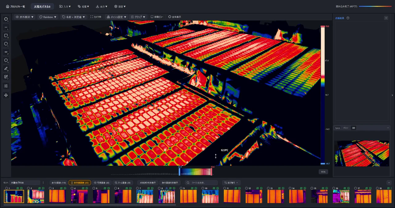
Generate 3D Models from Drone Photos — Build Temperature-Colored (Thermal) 3D Models with CRITIR
Learn how to automatically generate 3D models of buildings and structures from drone or ground-camera photos. With CRITIR, you get a visible-light 3D model plus a temperature-colored thermal 3D model, all linked to measurements and report output — streamlining inspection documentation for complex facades, equipment, and solar panels.
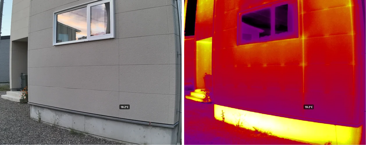
Emissivity and reflected temperature on thermal cameras: why your readings don't match, and how to fix them
Thermal camera readings that disagree with a contact thermometer, windows and metal that look impossibly cold — most of the time it is not a faulty camera but emissivity and reflected temperature settings. This guide explains what a thermal camera actually measures, lists typical emissivity values by material, shows how to measure reflected temperature with aluminum foil, and covers distance and humidity, why metal and glass are hard, and how to correct the settings after capture.
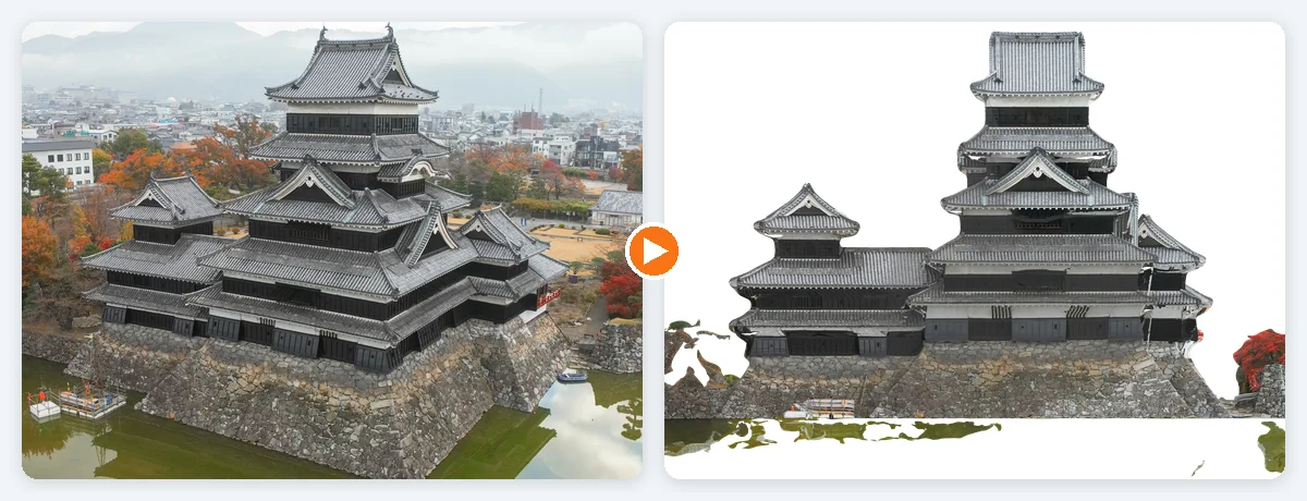
What is an orthophoto? How it differs from a photo, explained with diagrams — from aerial maps to building facades
A visual introduction to orthophotos (orthoimages) and how they differ from ordinary photos. Covers relief displacement (why tall buildings lean outward), true orthophotos, the four steps from photos to an orthophoto, map orthos versus facade orthos, and the conditions where orthophotos fail — with real examples from Matsumoto Castle and a retaining wall.